
keyword: 12V 1A EU adapter








HOME › SOLUTIONS › Phased-Array Antenna Power
SOLUTIONS / COMMERCIAL SPACE
Commercial space power solutions — from the platform bus to T/R modules.
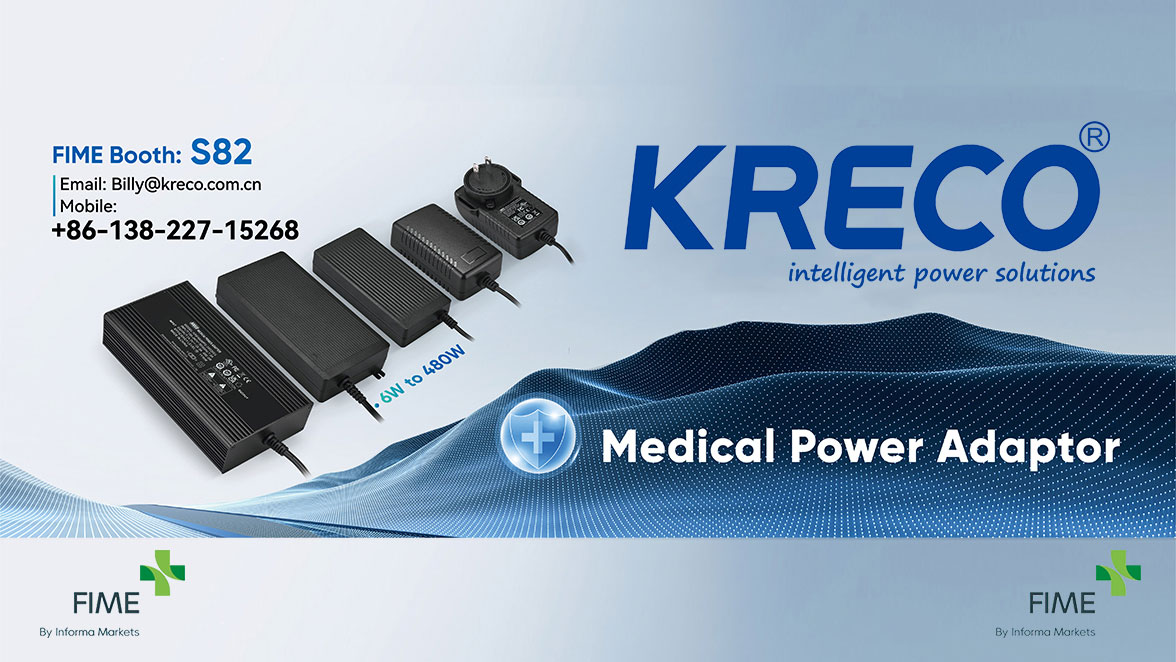
Image 1 — Hero visual.
Important notice on scope, standards and certification
This page describes KRECO's current engineering and OEM/ODM work on phased-array antenna power for commercial space programmes. It does not claim AS9100 certification, space qualification, flight heritage, airworthiness approval, DO-160 qualification, radiation-hardened part certification, or any named customer, satellite, launch or mission. Applicable standards, bus categories, component grades, radiation levels, test levels and acceptance evidence are frozen per programme in the interface control document and statement of work, and confirmed by test reports, certificates of conformity and, where required, customer audit before release. All standards named below are engineering references, not certification claims.
In short: KRECO designs and supplies the power chain for phased-array radar antennas in commercial space — from the platform bus, through protection and inrush control, isolated low-noise DC-DC conversion, tile-level distribution, sequencing and telemetry, to the pulsed T/R module load. The antenna is not a steady load: it switches between transmit and receive at pulse repetition rates from a few hertz to kilohertz, with peak power approaching ten times average power. Our job is to hold the rails steady, keep noise out of the RF chain, isolate faults to a single sub-array, and repeat it consistently across a constellation build.
KRECO currently supports customers on phased-array antenna power in the following application groups:
| Application | Typical Power Question |
|---|---|
| Spaceborne phased-array payloads — SAR / earth-observation, communication and data-relay flat-panel arrays on LEO smallsat and microsat platforms | Holding regulation through pulsed TX/RX load without modulating the spacecraft bus; SWaP-C and conduction-cooled packaging |
| Ground segment arrays — gateway, TT&C and calibration flat-panel phased arrays | Many independent rails, sequencing, per-rail telemetry, N+1 supply and graceful degradation |
| Transportable and mobile ground stations | Wide input range, generator / battery / mains transfer, vibration and thermal cycling |
| Integration, EGSE and burn-in benches | Programmable rails, automated per-rail test, fault injection and logged acceptance data |
Scope boundary. This sub-section is about commercial space. Airborne avionics power — which follows an RTCA DO-160G / MIL-STD-704F aircraft-bus baseline — is a different programme baseline and is not covered here. Applying an airborne qualification matrix to a spacecraft payload, or vice versa, produces the wrong design. See §8 for how the reference standards are separated.
| Challenge | What It Means Electrically | Design Response |
|---|---|---|
| Pulsed, high-slew load | T/R modules switch TX/RX at PRF from a few Hz to kHz; peak / average power ratio can approach 10:1; current slew can reach tens of A/µs | Low output impedance, fast transient loop, local hold-up capacitance or active power decoupling so the input current stays flat and the bus is not pulsed |
| Many rails, many zones | Thousands of elements grouped into tiles / sub-arrays; two common architectures: central bus → intermediate bus → PoL, or isolated DC-DC placed near each tile | Independent enable and sequencing per rail, fault isolation per zone, OR-ing / cross-strap, per-rail V/I/T telemetry |
| Noise couples into RF | Ripple and switching noise modulate the PA, degrading phase noise, spurs, EVM and SAR image quality; typical targets are tens of mVpp or lower | Low-noise topology, switch-frequency synchronisation or spread spectrum, multi-stage filtering, shielding, controlled return-current paths |
| SWaP-C and heat in vacuum | Efficiency gain of ~1 percentage point can cut array temperature rise by roughly 0.5 °C; in vacuum there is no convection | Soft-switching topologies, synchronous rectification, interleaving, conduction-cooled housing, thermally conductive potting |
| Constellation repeatability | A design that works once but drifts between lots is useless for multi-satellite builds | Frozen baseline, derating and DFMEA, automated test, lot traceability, PCN control |
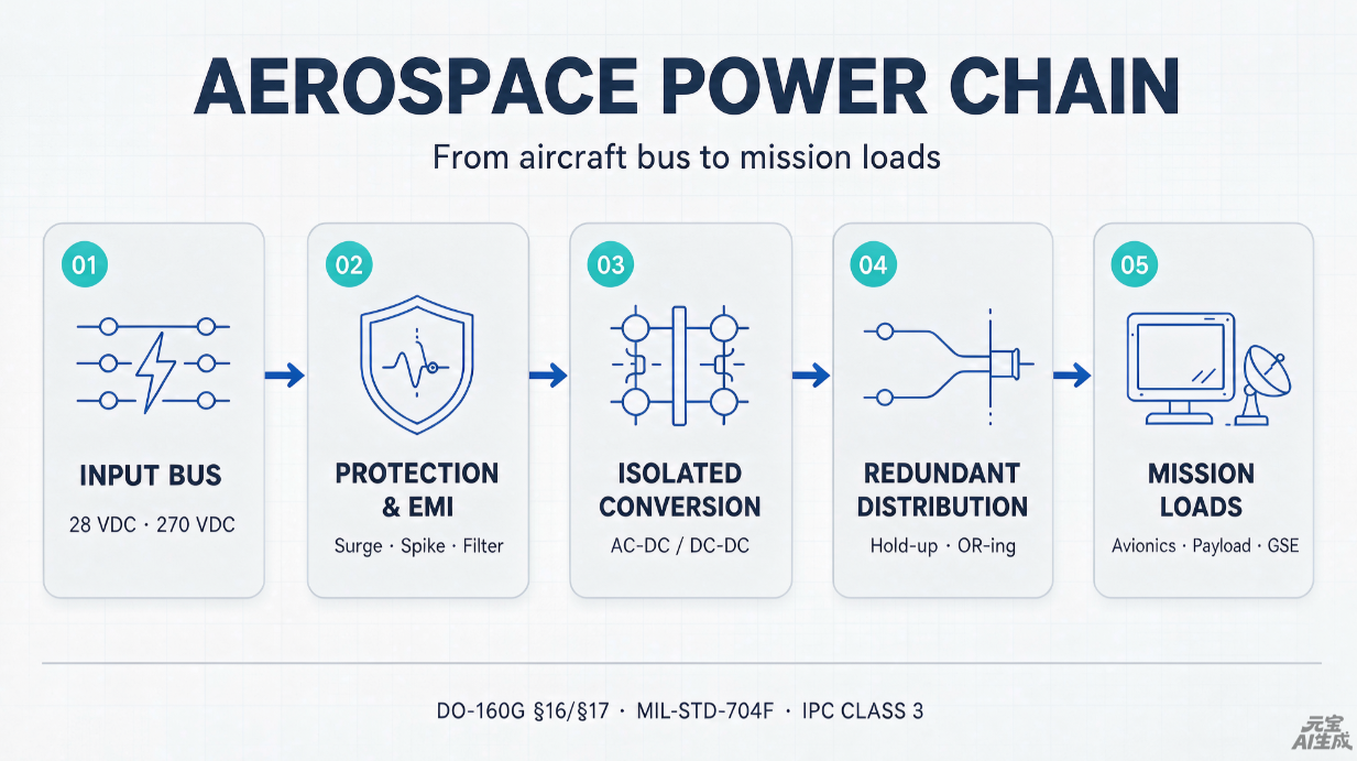
Image 2 — Power chain from the platform bus to T/R modules.
| Stage | Function | Items Frozen in the ICD |
|---|---|---|
| 01 Platform bus | Regulated or unregulated spacecraft / station bus; typical 28 V, 50 V and 100 V classes | Nominal and abnormal voltage range, bus ripple, transient limits, source impedance, fault tolerance and emission limits |
| 02 Protection & EMI | Inrush limiting and pre-charge, LCL / RLCL or solid-state power controller, EMI filter, undervoltage and reverse-current behaviour | Current class, trip-off time, retrigger behaviour, input filter charge energy, conducted emission and susceptibility limits |
| 03 Isolated DC-DC | Isolated, low-noise, multi-output conversion to tile rails; soft-switching, synchronous rectification, interleaving and digital control where justified | Number of outputs, voltage / current / tolerance, cross-regulation, transient response, ripple and noise, efficiency at operating points |
| 04 Tile distribution | Sequencing, per-rail enable, OR-ing / cross-strap, hold-up, telemetry, fault isolation and graceful degradation (shed sub-arrays, keep the main beam) | Power-up / power-down order, telemetry format and rate, fault thresholds, isolation and recovery behaviour |
| 05 T/R modules & beam control | Pulsed PA / LNA / phase-shifter / attenuator loads and the beam-steering controller | Pulse profile, peak / average ratio, PRF, allowable rail droop, local decoupling responsibility split |
ECSS-E-ST-20-20C provides useful reference numbers for the bus interface: 28 V and 50 V regulated / unregulated reference buses, bus ripple in the order of ±500 mVpp across 30 Hz to 50 MHz, and transient limits for 50 % load steps at 1 A/µs. These are reference values for LCL / RLCL-based main-bus distribution — the controlling numbers are always those in your platform ICD.
| ICD Item | Why It Matters |
|---|---|
| Bus voltage range (nominal / abnormal / transient) | Defines the input envelope, derating and survival requirements |
| Bus ripple, dI/dt and source impedance | Determines input filter design and negative-impedance stability of the converter |
| Inrush, pre-charge and input capacitance | Protects LCL / RLCL trip settings and prevents bus disturbance at switch-on |
| Ripple and noise injected back into the bus | Protects other payloads sharing the same bus |
| Output rails: count, voltage, current, tolerance | Defines the conversion topology and magnetics |
| Transient response and hold-up under pulse load | The single most important electrical requirement for a T/R supply |
| Per-rail ripple and noise limits | Directly linked to phase noise, spurs and image quality |
| Power-up / power-down sequencing and enables | Prevents latch-up and uncontrolled beam states |
| Protection: OVP / OCP / OTP / SCP / UVP, trip and recovery | Keeps a single tile fault from collapsing the whole array |
| Telemetry / telecommand: V, I, temperature, status | Enables autonomous degradation and ground diagnosis |
| Grounding, return paths and isolation | Controls common-mode noise into the RF chain |
| Connectors, harness, shielding and strain relief | Array cabling is dense, weight-sensitive and vibration-exposed |
| SWaP-C budget, mounting and thermal interface | Determines packaging, potting and conduction path |
| Environment: thermal cycling, vacuum, outgassing, vibration, EMC | Set by orbit / site and mission profile |
| Radiation: TID / SEE target and parts strategy | Set by orbit, shielding and mission life; see §5 |
| Quality: documentation, FAI, CoC, traceability, PCN | Set by the customer's quality agreement; see §6 |
NewSpace programmes usually adopt a radiation-tolerant / space-COTS strategy rather than fully radiation-hardened parts, trading cost and lead time against mission life. The applicable level is a project decision, not a default supplier claim.
| Gate | Typical Activities |
|---|---|
| Design | Derating, DFMEA / FMECA, worst-case analysis, power and energy budget with margin, thermal and stability analysis, parts and materials plan |
| EVT | Prototype build, pulsed-load transient characterisation, ripple and noise measurement, efficiency map, thermal survey |
| DVT | Thermal cycling, vibration / shock, EMC, burn-in, fault injection on protection and isolation paths, telemetry verification |
| PVT / series | Automated per-rail ATE, lot-level material traceability, serialisation, controlled rework, CoC, first article inspection documentation where specified |
| Change control | Formal PCN before any component, process or firmware change; counterfeit-part avoidance; last-time-buy planning and supply buffer |
Workmanship detail that is often missed: IPC-A-610 / J-STD-001 Class 3 governs board-level assembly. IPC/WHMA-A-620 Class 3 for cable and harness assemblies must be written explicitly on the drawing or purchase order — board Class 3 does not automatically extend to the array harness. This matters on phased arrays, where the harness is dense, shielded and vibration-exposed.
Whether AS9100D / AS9102 first article inspection, ECSS documentation clauses or a customer-specific quality agreement are invoked is a contractual decision for each programme. KRECO works to the quality baseline the customer freezes.
KRECO Group was founded in 2008 (Equity Code 891359, Medical Registration No. 20200118#) and owns the European / American brand IPSKRE. Its production base is in Zhongshan in the Greater Bay Area. The group is an IEC 60601 medical and industrial power manufacturer with in-group magnetics, cable assembly and charger capability — a useful combination for phased-array antenna power, where the power module, the magnetics and the harness have to be engineered as one system.
| In-Group Capability | Applied To Phased-Array Power |
|---|---|
| IEC 60601 medical adapters, 6 W–480 W — KRE006MPS–KRE072MPS wall-mount and KRE048MPS–KRE480MPS desktop (e.g. 48 V 10 A), 4th Edition, 2×MOPP, leakage below 100 µA | Low-leakage, low-noise isolated conversion discipline, controlled insulation systems and regulated manufacturing processes |
| Industrial adapters and battery charger programmes (5 W–5000 W class), IEC 62368 / IEC 61558 experience | Multi-output conversion, thermal design and high-volume process control |
| Toroidal transformers and custom magnetics | Leakage-inductance and turns-ratio control for resonant / soft-switching topologies; lot-to-lot consistency; low stray field |
| Wire harness, power cord and cable assemblies | Shielded tile harnesses, controlled impedance and return paths, strain relief, Class 3 workmanship when specified |
| Potting, shielding and rugged enclosures | Conduction-cooled, low-outgassing packaging for vacuum and launch environments |
| ATE, burn-in and OEM/ODM customisation | Per-rail automated test, serialisation and PCN-controlled series supply |
| iPSKRE SatNet Power Supply (separate product line) | Satellite-internet terminal power: wide-input DC-DC, proprietary passive PoE, DC-UPS and IP66 enclosures — an adjacent capability for ground-segment projects |
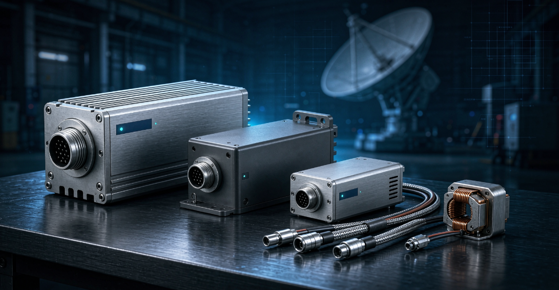
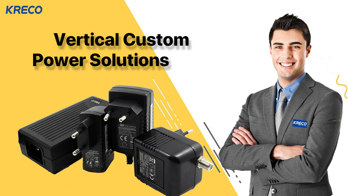
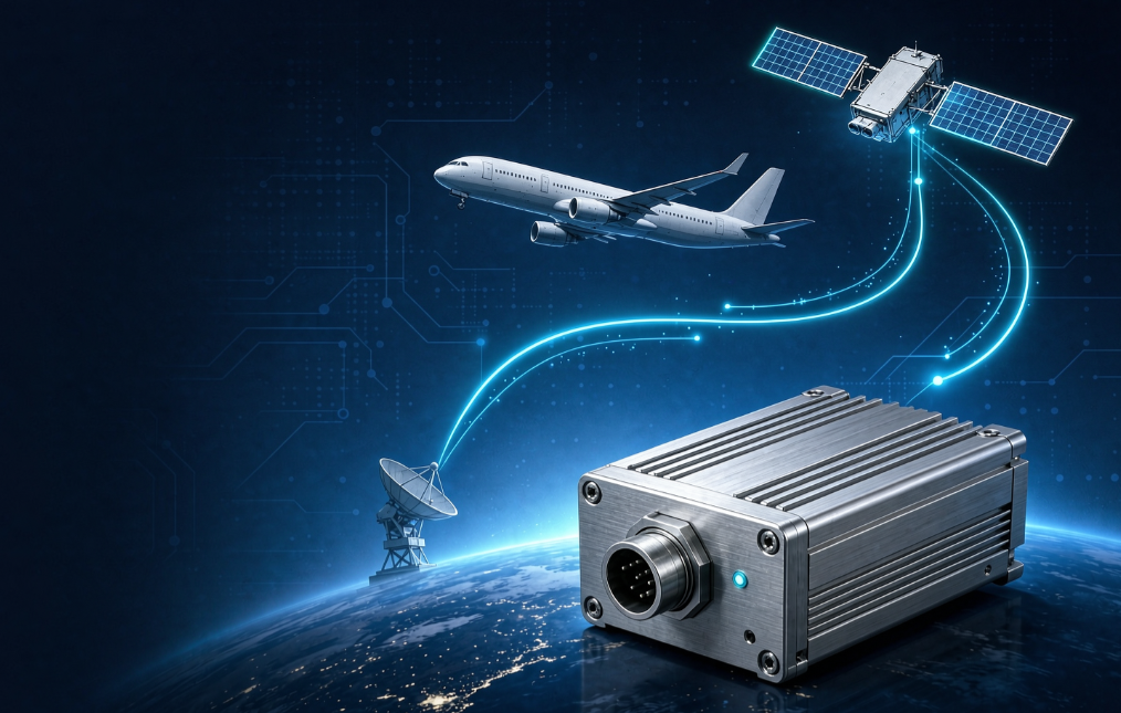
Image 3 — Hardware family concept, illustrative only; no model numbers or performance claims.
| Reference | Role Here | Caveat |
|---|---|---|
| Platform ICD / customer SOW | Controlling document for bus, rails, sequencing, telemetry, environment and acceptance | Always takes precedence over any generic standard |
| ECSS-E-ST-20C / ECSS-E-ST-20-20C + ECSS-E-HB-20-20A (also EN 16603-20-20:2018) | Reference for main-bus distribution by LCL / RLCL / HLCL, current classes, trip-off behaviour, bus ripple and transient limits, power budget margin | Written for LCL/RLCL-based satellite main-bus distribution; explicitly excludes telecom architectures protected by fuses. Apply by analysis, not by blanket invocation |
| ASTM E595 | Vacuum outgassing screening for materials (TML / CVCM) | Material-level test; does not qualify an assembly |
| MIL-STD-883 Method 1019 / RLAT | Reference method for TID characterisation of parts where radiation screening is specified | Level is set by orbit, shielding and mission life |
| IPC-A-610 / J-STD-001 Class 3 | Board-level workmanship | Does not automatically cover harnesses |
| IPC/WHMA-A-620 Class 3 | Cable and harness assembly workmanship | Must be stated explicitly on drawing / PO |
| AS9100D / AS9102 | Quality management system and first article inspection | Only when contractually invoked; no certification is claimed here |
| RTCA DO-160G / MIL-STD-704F | Airborne baseline — not this scope | DO-160G (2010) is the current edition referenced by FAA AC 21-16G; DO-160H was in final review during 2026 and had not been published. Freeze the edition in the airborne requirements baseline. Do not apply it to a spacecraft payload by default |
The power chain from the platform bus to the T/R modules: protection and inrush control, isolated low-noise multi-output DC-DC, tile-level sequencing, telemetry and fault isolation, and the hold-up / decoupling strategy for the pulsed load — plus the magnetics and shielded harnesses that go with it.
Because the load can jump from receive to transmit in microseconds, with peak power approaching ten times average power. Without low output impedance and local energy storage the rails droop, the bus is modulated, and supply noise appears as phase noise and spurs in the RF output.
The envelope comes from your ICD. Typical commercial-space discussions involve 28 V, 50 V and 100 V classes, regulated or unregulated; ECSS-E-ST-20-20C gives 28 V and 50 V reference buses. We do not publish a fixed "supported range" independent of the programme.
This page makes no such claim. Standards, grades and evidence are agreed per programme and confirmed by test reports, CoC and, where required, customer audit. See the notice at the top of this page.
Yes — toroidal transformers, custom magnetics, shielded cable assemblies and potted enclosures are in-group capabilities. Remember to call out IPC/WHMA-A-620 Class 3 explicitly for harnesses.
Those belong to a separate airborne baseline. This sub-section covers commercial space; if a programme includes both aircraft and spacecraft equipment, we establish two separate requirement baselines.
Discuss your phased-array antenna power requirement
Send your ICD draft, pulse profile, rail list and mission environment. We will respond with a proposed topology, the interface items that still need freezing, and a verification plan.
sales@kreco.com.cn | www.kreco.com.cn | iPSKRE Power Ecosystem
Engineering references consulted for this page include ECSS-E-ST-20C / ECSS-E-ST-20-20C and ECSS-E-HB-20-20A (LCL / RLCL main-bus distribution, 28 V and 50 V reference buses, bus ripple and transient limits), EN 16603-20-20:2018, ASTM E595 (TML / CVCM outgassing), MIL-STD-883 Method 1019 and RLAT practice for radiation characterisation, IPC-A-610 / J-STD-001 and IPC/WHMA-A-620 Class 3 workmanship, and RTCA DO-160G with FAA AC 21-16G for the airborne baseline. Pulsed-load behaviour, efficiency / thermal relationships and topology options reflect published phased-array power engineering practice. Numerical values are indicative reference points, not KRECO product specifications — your ICD governs.
KRECO Group is not affiliated with, endorsed by, or a supplier to any named satellite, launch or radar prime unless a contract states otherwise. No customer, mission, flight heritage, AS9100 certification, space qualification, airworthiness approval or radiation-hardened part certification is claimed. SatNet Power Supply is a separate Starlink-compatible product line; KRECO is not affiliated with or endorsed by Starlink / SpaceX. Images are illustrative concepts.
Issued 20 November 2026. Verify the final canonical URL, navigation path and CDN image URLs before publishing, and keep the compliance notice visible.
 粤ICP备19148190号