
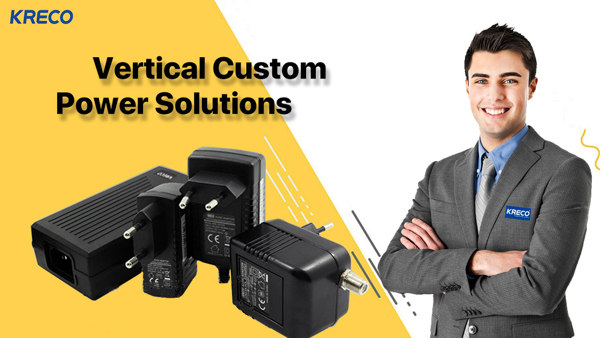

keyword: 12V 1A EU adapter








KRECO | Starlink & SatNet Power Supply FAQ Series — Article 21
Short answer: Standard 4 / 4 X and Mini are land / Roam-class terminals — they are not licensed for continuous in-motion use or offshore maritime service. For vehicles online while moving and for vessels offshore, Starlink requires the Performance (Gen 2) terminal (formerly Flat High Performance) — the in-motion capable SatNet Power Supply class — plus the right plan: Mobile Priority for land mobility, Maritime for vessels (hardware alone does not grant service rights). Its power profile: 110–150W average, 200W max, 140° FOV, IP56 dish / IP66 PSU, −30 °C to 50 °C, snow melt up to 75 mm/h, wind survivable 280 kph+, ships with a Wedge Mount, 25 m dish cable and 5 m Ethernet. PSU input is 100–240V ~ 6.3A (AC-only, no native DC) with a dedicated earth terminal, feeding proprietary passive PoE on 1236+ / 4578- (not 802.3af/at). Energy: ≈2.6–3.6 kWh/day; 1000Wh gives only ≈5.7 h @150W. Best DC path is a 340W-class DC-DC injector (≈54V / 6.3A) from 12V or 24V (≈11.5–30V input); AC route needs a pure sine wave inverter, ≥1000W recommended. Marine installs additionally require ABYC tinned cable, bonding/grounding, a galvanic isolator onshore power, outdoor Ethernet/PoE SPD and mast lightning protection.
| Terminal | Class | In-Motion? | Offshore Maritime? | Required Plan |
|---|---|---|---|---|
| Standard 4 / Standard 4 X | Land / Roam | NO | NO | Residential / Roam (stationary use) |
| Starlink Mini | Land / Roam (portable) | NO | NO (inland/coastal stationary only where permitted) | Roam / Mobile (confirm terms) |
| Enterprise | Fixed business site | NO | NO | Fixed business / Priority |
|
Performance (Gen 2) (formerly Flat High Performance) |
Mobility & maritime | YES | YES | Mobile Priority (land) / Maritime (vessel) |
Critical rule: hardware capability ≠ service permission. A Performance (Gen 2) / Flat High Performance terminal used on a moving vehicle without Mobile Priority, or on a vessel offshore without a Maritime plan, is outside the licensed use case. Confirm your plan, region and fair-use terms before any in-motion or vessel installation. This guide covers the power design for that licensed hardware.
| Parameter | Value |
|---|---|
| Average power usage | 110–150W; 200W max (stated) |
| PSU input | 100–240V AC, 6.3A, 50–60 Hz — AC-only, no native low-voltage DC input |
| Dish-side feed | Proprietary passive PoE, +V on pins 1,2,3,6 / −V on pins 4,5,7,8 (1236+ / 4578-) — NOT IEEE 802.3af/at/bt |
| PSU rating | IP66, −30 °C to 50 °C, ≈1.5 kg, ≈288 × 133 × 46 mm, wall mount, LED, dedicated earth terminal |
| Dish rating | IP56; electronic phased array, 140° FOV; wind survivable 280 kph+ |
| Snow melt | Up to 75 mm/h (3 in/h) — the highest in the Starlink range |
| Cables supplied | 25 m (82 ft) Starlink cable, 5 m Ethernet cable, 1.8 m AC cable, Wedge Mount Kit |
| DC conversion (third-party) | 340W class injector + boost converter ≈54V / 6.3A, from 12V or 24V battery, wide input ≈11.5–30V DC, with surge, OVP/UVP, OCP, reverse-polarity and battery-discharge protection |
| Load Case | Load | Daily Energy | Runtime (Wh × 0.85 ÷ W) |
|---|---|---|---|
| Typical average | 110W | ≈2.6 kWh | 1000Wh ≈7.7 h |
| High demand / heater duty | 150W | ≈3.6 kWh | 1000Wh ≈5.7 h |
| Vehicle / vessel bank 12V 200Ah (2.56 kWh) | 150W | — | ≈14.5 h (≈19.8 h @110W) |
| Vessel bank 24V 200Ah (5.12 kWh) | 150W | — | ≈29.0 h (≈39.6 h @110W) |
| Vessel bank 48V 200Ah (10.24 kWh) | 150W | — | ≈58 h (≈79 h @110W) |
| Solar (off-grid / anchorage) | — | 2.6–3.6 kWh/day | ≈800–1200W+ array (at 5 peak sun hours × 0.7) |
Formulas: Runtime (h) ≈ Capacity (Wh) × 0.85 ÷ Load (W); Required solar ≈ daily Wh ÷ (peak sun hours × 0.7). Always size for peak (200W max) and add 15–20% battery capacity for cold.
| Path | How | Best For / Cautions |
|---|---|---|
| 1. Original AC PSU (mains / shore / generator) | PSU 100–240V ~6.3A → dish via proprietary PoE | Simplest when AC is available. On vessels: must use a galvanic isolator / isolation transformer on shore power |
| 2. Pure sine wave inverter | Battery → inverter → AC PSU | Starlink guidance ≥500W, but for this class ≥1000W recommended (PSU nameplate 6.3A; dish peaks 200W). Modified/square wave will not run it properly |
| 3. DC-DC (RECOMMENDED for mobile/marine) | 12V or 24V battery → 340W-class DC-DC injector/boost → ≈54V / 6.3A → dish | No inverter loss (15–30% saved), handles engine/alternator voltage swings (≈11.5–30V input). For 48V banks (51.2V) use a wide-input (e.g. 10–60V) unit |
| 4. Wide-input DC-DC (KRECO-class) | 10–60V DC input → regulated high-voltage output, 340W class | One module covers 12V / 24V / 48V and 51.2V LiFePO4 banks — ideal for larger vessels and mixed fleets |
| Step | Requirement |
|---|---|
| Mounting | Use the supplied Wedge Mount Kit or a vibration-resistant vehicle mount; bolt it down — never rely on suction alone at speed. Keep a clear sky view; avoid roof racks, light bars and roof-mounted obstructions |
| System voltage | Most vans/trucks/RVs are 12V; larger vehicles/coaches 24V. Confirm before selecting the converter (a 12/24V unit accepts ≈11.5–30V) |
| Fusing | Fuse the positive feed at the battery. For a 340W-class load: ≈40A class at 12V, ≈20–25A class at 24V (size per the converter's stated input current plus 25% margin) |
| Cable gauge | 12V → 10 AWG (short run, keep <5 m where possible); 24V → 12 AWG. Higher voltage = lower current = less drop — prefer 24V on larger builds |
| Charging while driving | Engine alternator via a DC-DC charger (30–50A class) or a dedicated house battery; at 150W the dish draws ≈12.5A at 12V / ≈6.3A at 24V — the alternator easily covers it while driving, but a buffer battery is essential when parked |
| Electrical environment | Vehicle power is dirty: cranking dips (≈11.5V), charging rise (≈14.4V at 12V / ≈28–29V at 24V), and load-dump spikes. Use a wide-input converter with surge, OVP/UVP, OCP and reverse-polarity protection |
| Converter location | Mount in a dry, ventilated compartment; keep the proprietary dish cable within the 25 m supplied length; add strain relief and drip loops at every entry |
| Vibration & heat | PSU rated −30 °C to 50 °C — do not mount in direct engine-bay heat; secure all connectors against vibration; use UV-resistant outdoor cable |
| Service plan | Confirm Mobile Priority coverage for your route/region before relying on in-motion connectivity |
| Requirement | What It Means for Your SatNet Power Supply |
|---|---|
| Marine-grade tinned cable | Use tinned copper throughout — bare copper corrodes rapidly in a marine atmosphere and creates high-resistance faults that mimic POE_INSUFFICIENT |
| ABYC overcurrent protection | A fuse or breaker on every positive conductor, as close to the source as practical; correct gauge for the run; no un-fused taps |
| Bonding & grounding | Bond the DC negative / ground system per ABYC; the PSU has a dedicated earth terminal — bond it properly. Avoid ground loops that cause electrolysis |
| Galvanic isolation (shore power) | Install a galvanic isolator or isolation transformer on the shore-power connection — mandatory to protect the vessel and the Starlink PSU from shore-side corrosion currents |
| Surge / lightning | Fit an outdoor-rated Ethernet/PoE SPD on the dish cable; bond/ground the mast; add an air terminal if the mast is the highest point. Masts are prime strike points |
| Corrosion & sealing | IP66/IP68 enclosures with cable glands, drip loops and dielectric grease on non-proprietary connectors; keep the PSU out of bilge water and spray |
| House bank sizing | At 110–150W the terminal uses ≈2.6–3.6 kWh/day — that is ≈220–300Ah/day at 12V or ≈110–150Ah/day at 24V. Size the bank for your intended hours between charges/generator runs |
| Charging sources | Engine alternator + DC-DC charger, generator, solar (800–1200W+), or shore power through the isolator. A DC-DC feed avoids inverter loss — the preferred marine path |
| Mounting & interference | Secure against vibration and wave slap; keep clear of radar, rigging and sails; maintain a clear horizon-to-horizon sky view |
| Service plan | Offshore use requires a Maritime plan with the Performance (Gen 2) / Flat High Performance terminal — confirm coverage for your cruising grounds |
KRECO Group — an IEC 60601 medical & industrial power manufacturer since 2008 (Equity Code 891359, Medical Reg. 20200118#, FIME Silver Sponsor) — is developing Starlink-compatible SatNet Power Supply OEM/ODM solutions under the iPSKRE Power Ecosystem, purpose-engineered for in-motion and maritime deployments:
Inquire Now: sales@kreco.com.cn | iPSKRE Power Ecosystem | Starlink-compatible SatNet Power Supply OEM/ODM — 340W-class DC-DC, passive PoE, marine enclosures & DC-UPS under development.
Based on Starlink official Specifications & Help Center (Performance (Gen 2) / Flat High Performance: average power usage 110–150W with 200W max; electronic phased array, 140° FOV; dish IP56, power supply IP66; −30 °C to 50 °C; snow melt up to 75 mm/h (3 in/h); wind survivable above 280 kph; Wedge Mount Kit; 25 m (82 ft) Starlink cable; 5 m Ethernet; 1.8 m AC cable; power supply input 100–240V ~ 6.3A 50–60 Hz, ≈1.5 kg, ≈288 × 133 × 46 mm, wall mount, LED, dedicated earth terminal; proprietary passive PoE with +V on pins 1,2,3,6 and −V on pins 4,5,7,8; in-motion capable with Mobile Priority / Maritime service plans) and 2026 in-motion & marine installation references; third-party FHP DC solutions are typically 340W class (≈54V / 6.3A from 12V or 24V, ≈11.5–30V DC input). Runtime uses Wh × 0.85 ÷ W. KRECO is not affiliated with or endorsed by Starlink/SpaceX; Starlink-compatible SatNet Power Supply modules are under development. Hardware capability does not grant service rights — confirm your Mobile Priority / Maritime plan and regional availability. Always follow ABYC and local electrical code for marine and vehicle installations, use licensed installers for mains, grounding and lightning-protection work, keep Snow Melt enabled, and keep original Starlink parts for warranty.
 粤ICP备19148190号